
- Supply Systems & Components
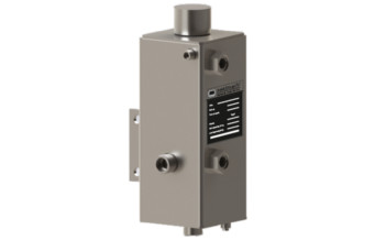
QFS2000
- Circulation in accordance with API 682 / ISO 21049: Plan 51, Plan 52
- Quench fluid supply system is employed for applications in sealing systems with a wide variety of operating parameters for supplying quench fluid to double and tandem mechanical seals. They act as a convenient fluid reservoir. The exchange of fluid takes place by the thermosiphon principle or by forced circulation, for example with a pumping screw. The QFS2000 stainless steel tank is equipped with sight-glasses for monitoring the MIN/MAX level and can be fastened with a lug fixture. The leakage overflow can be selectively discharged.
Download PDF
Details
-
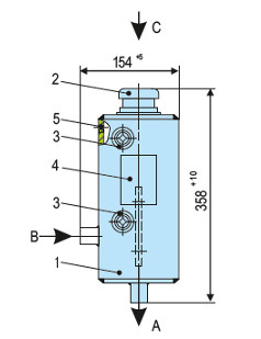
1
Storage tank (capacity 3L)
-
2
Inlet filter with vented cap
-
3
Sight-glass or level switch
-
4
Name plate
-
5
Overflow G 1/8
- Designed for varied applications due to construction in stainless steel with borosilicate sight-glasses suitable for highly corrosive media
- Reliability in operation due to the design of combined filling and ventilation filter in the hand refill pump
- Construction design for operating pressure up to 200 °C
- Discharge of leakage is achieved due to integrated overflow design
- To monitor the fluid volume a level switch can be installed instead of sight glass
Quench fluid systems are employed:
- To absorb leakage
- To monitor the leakage rate (e.g. through periodic reading of the level in the tank)
- To lubricate and to cool the outboard mechanical seal in a tandem arrangement
- To prevent icing
- To protect against dry running
- To stabilize the lubricating film
- To exclude air from the media in order to prevent a reaction with oxygen in the air
- Chemical industry
- Petrochemical industry
- Oil and gas industry
- Refining technology
- Pulp and paper industry
- Food and beverage industry
- Install the quench fluid tank approx. 1 … 2 m (3.3 … 6.6 ft) above the mechanical seal. Install connection pipes to the mechanical seal with low flow resistance. Pipes must vent automatically in the direction of the tank. It is imperative that air pockets are prevented. The minimum filling level must always be above the connection socket at the side (in the case of the thermosiphon principle).
- Quench fluid systems can be operated in two different modes:
- Dead-end quench (Plan 51):
Quench fluid from an elevated tank. The characteristic feature of this principle is that no heat is dissipated by the system. - Circulation (Plan 52):
Quench fluid from an elevated tank; external tank, pressureless; thermosiphon or forced circulation. In this case heat is dissipated by the circulation. Cooling capacity by convection is minimal, however.
Other products
-
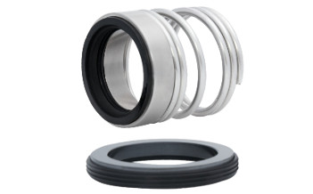
U300N
Single seal configuration, Unbalanced Design, Dependent of direction of rotation, For plain shafts
Learn more
-
U200N
Single seal configuration, Unbalanced Design, Dependent of direction of rotation, For plain shafts…
Learn more
-
UG943
Single seal configuration, Unbalanced design, Independent of direction of rotation, For plain…
Learn more
-
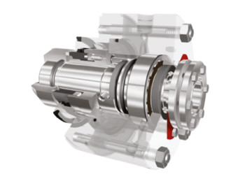
UR-D
Dual seal configuration, Unbalanced design, Independent of direction of rotation…
Learn more