
- Supply Systems & Components
BFS6000
- Circulation in accordance with API 682 / ISO 21049: Plan 52, Plan 53A
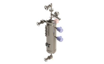
- The BFS6000 range of vessels range conforms to API 682 guidelines. The vessels are equipped with all essential connections for fitting additional components. The BFS 6000 system is available in standard sizes with flat ends, sight-glasses for level monitoring and with or without cooling coil. BFS 6000 system is equipped as a standard with all the necessary system connections and brackets.
Download PDF
Details
-
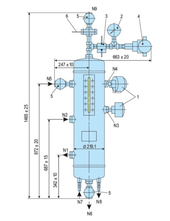
1
Level switch
-
2
Manometer
-
3
Manifold
-
4
Pressure switch
-
5
Shut-off valve
-
6
Orifice
- For optimum and simple cleaning of the vessel interior, a design variant is available which can be dismantled
- Modular design combination available with a wide variety of system components and instruments selection possible, such as level switch, circulation pump, hand refill pump, thermometer, base frame etc.
- Construction of the BFS 6000 is designed for demanding operating conditions up to 50 bar / 200°C
- Optimum visual is achieved for level monitoring through a robust design with weld-pad type sight glass
- The BFS system performs all the basic functions of a buffer/barrier system for the operation of double seals:
- To pressurize the buffer chamber
- Leakage compensation
- Buffer/barrier fluid is circulated by thermosiphon effect
- Or forced circulation system
- To cool the seal
- To selectively absorb product leakage and prevent dry
- Running (tandem arrangement)
- Use compressed air or nitrogen for pressurization; pressurization is monitored by a pressure switch.
The incorporated level switch issues a signal whenever the level of buffer/barrier fluid is too low.
- Operating and installation diagram for a BFS6000 system
The BFS vessel must always be installed higher than the mechanical seal. The buffer/barrier fluid flows via the return pipe into the vessel and is cooled. The exchange of fluid takes place by the thermosiphon principle or by forced circulation, e.g. with a pumping screw. Connection pipes to the seal should be designed with as little resistance as possible.
- Refining technology
- Oil and gas industry
- Chemical industry
- Petrochemical industry
- PED 2014/68/EU
- ASME VIII, Div. 1
Other products
-
U300N
Single seal configuration, Unbalanced Design, Dependent of direction of rotation, For plain shafts
Learn more
-
U200N
Single seal configuration, Unbalanced Design, Dependent of direction of rotation, For plain shafts…
Learn more
-
UG943
Single seal configuration, Unbalanced design, Independent of direction of rotation, For plain…
Learn more
-
UR-D
Dual seal configuration, Unbalanced design, Independent of direction of rotation…
Learn more