- Supply Systems & Components
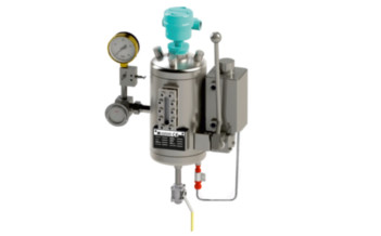
BFS2000
- BFS 2000 system is employed for applications in sealing systems with a wide variety of operating parameters for supplying buffer/barrier fluid to double and tandem mechanical seals. The BFS 2000 system is available in standard sizes with flat ends, sight-glasses for level monitoring and with or without cooling coil. BFS 2000 system is equipped as a standard with all the necessary system connections and brackets. Modular design combination available with a wide variety of system components and instruments selection possible such as, level switch, circulation pump, hand refill pump, thermometer, base frame etc.
- Circulation in accordance with API 682 / ISO 21049: Plan 52, Plan 53A
Download PDF
Details
-
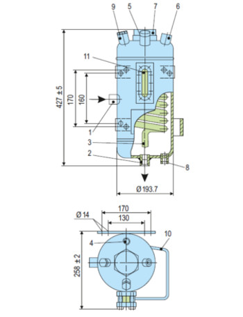
1
Buffer/barrier fluid IN (G1/2")
-
2
Buffer/Barrier fluid OUT (G1/2")
-
3
Cooling water IN (G1/2")
-
4
Cooling water OUT (G1/2")
-
5
Filling connection with plug (G1/2")
-
6
Pressure gas connection (G1/2")
-
7
Connection for level switch or level indicator (G2")
-
8
Connection for hand refill pump (G1/2")
-
9
Universal connection (G1/2") for safety valve, flare,etc
-
10
Bracket for hand refill pump
-
11
Sight-glass
- Available with or without cooling coil
- Optimum draining and venting is achieved because of the design of cooling water connections at top (OUT) and bottom (IN)
- Sockets are designed with recessed gasket to avoid contamination of the circuit by thread sealant
- Construction of the BFS 2000 is designed for demanding operating conditions up to 30 bar / 200°C
- Design allows for varied applications due to construction in stainless steel with borosilicate sight-glasses
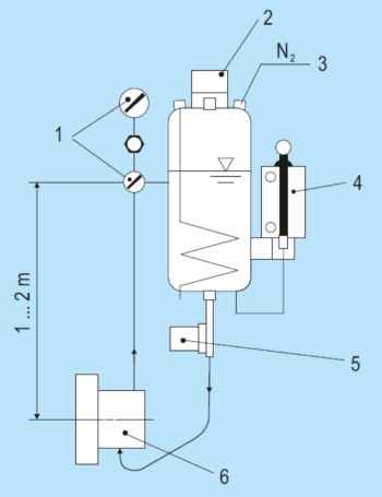
- The BFS system performs all the basic functions of a buffer/barrier system for the operation of double seals:
- To pressurize the buffer chamber
- Leakage compensation
- Buffer/barrier fluid is circulated by thermosiphon effect or external circulation system
- To cool the seal
- To selectively absorb product leakage and prevent dry running (tandem arrangement)
- Use compressed air or nitrogen for pressurization
- The BFS vessel must always be installed higher than the mechanical seal. The buffer/barrier fluid flows via the return pipe into the vessel and is cooled. The exchange of fluid takes place by the thermosiphon principle or by forced circulation, e.g. with a pumping screw. Connection pipes to the seal should be designed with as little resistance as possible.
- Measuring unit
- Level Switch
- From PCV, we recommend using a reverse controlled pressure control valve (PCV)
- Hand Refill Pump
- Circulating Pump
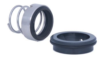
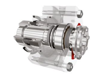
- Mechanical seal
- Chemical industry
- Oil and gas industry
- Petrochemical industry
- Refining technology
- PED 2014/68/EU (Design and production in accordance with EU Pressure Equipment Directive)
- ASME VIII, Div.1 (Design, calculation and production)
Other products
-
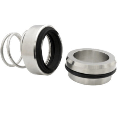
U300N
Single seal configuration, Unbalanced Design, Dependent of direction of rotation, For plain shafts
Learn more
-
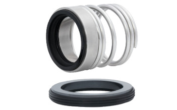
U200N
Single seal configuration, Unbalanced Design, Dependent of direction of rotation, For plain shafts…
Learn more
-
UG943
Single seal configuration, Unbalanced design, Independent of direction of rotation, For plain…
Learn more
-
UR-D
Dual seal configuration, Unbalanced design, Independent of direction of rotation…
Learn more